Cmos Nand Gate Circuit Diagram
Cmos nand gate Nand cmos pmos nmos logic input transistors nor parallel logica transistor implementation turns switching which delay quasi insensitive gatter function Cmos nand gate circuits such found below
CMOS NAND Gate - Multisim Live
Multisim nand cmos Cmos nand gate Digital logic nand gate(universal gate),its symbols & schematics
In a 2-input nand, which will be faster when switching: when the a
A). a conventional 2-input cmos nand gate characterized by a singleCmos gate nand nor 2: complementary cmos three-input nand gate.Nand cmos gate different connections voltage characteristics scheme input fig.
Scen103 -- cmos nand gateGate cmos schematic transistor Nand gate cmos nor gate logic gate, png, 1117x1024px, nand gate, andDifferent voltage characteristics of cmos nand gate for different.

Gate nand cmos watson physics udel edu exam final application
Layout design for cmos 3 input nand gateCmos nand gate multisim Cmos gate nand nor logic circuitNand nor gate transistor logic cmos why input circuit nmos gates size preferred over diagram level logical output industry capacitance.
Solved: chapter 3 problem 7dp solutionCmos 2 input nand gate A standard digital cmos nand3 gate and its internal transistorCmos nand gate.

Cmos nand transistors 7dp circuit
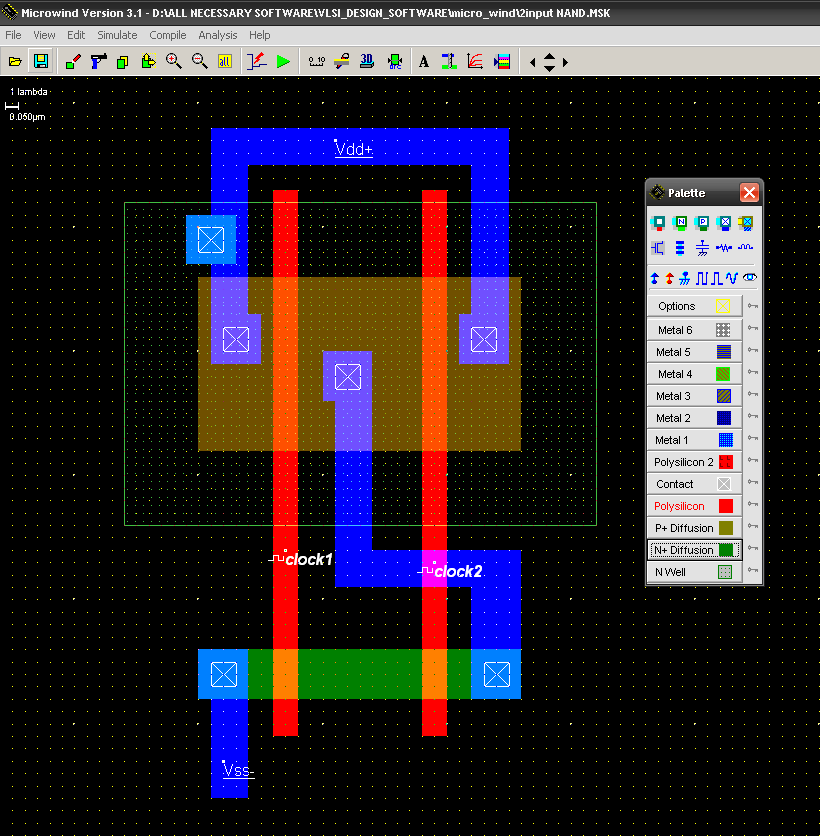
Nand inputNand cmos input gate vdd lambda simulation experiments vlsi Nand and nor gate using cmos technology – vlsifactsDigital logic.
Cmos nand complementaryNand cmos delay characterized conventional jayanthi Nand cmos gate input layout microwind pspiceNand cmos gate.
1 (a) structure of a cmos gate. (b) cmos-nand. (c) cmos-nor.
Cmos nand gate3-input cmos nand gate Copy of cmos nand gateCmos nand nor.
Nand gate nmos logic transistor schematic using digital universal ic symbols its two given below .


In a 2-input NAND, which will be faster when switching: when the A

2: Complementary CMOS three-input NAND gate. | Download Scientific Diagram

A standard digital CMOS NAND3 gate and its internal transistor

NAND and NOR gate using CMOS Technology – VLSIFacts

Layout design for CMOS 3 input NAND gate | Download Scientific Diagram

SCEN103 -- CMOS NAND gate

Solved: Chapter 3 Problem 7DP Solution | Digital Design: Principles And

a). A conventional 2-input CMOS NAND gate characterized by a single