Circuit Diagram Voltage Problem
Kirchoffs law for 3 loop circuit with multiple voltage supplies Voltage and current Solved consider the voltage divider bias circuit shown.
AC Circuit Analysis – Sources with Different Frequencies – Solved Problems
A circuit diagram of a three-phase voltage source Circuit ac sources analysis problems voltage different state steady source frequencies problem domain off frequency circuits solved electrical Circuit dc voltages theory tutorial voltage
Voltage and current in a practical circuit
Voltage in series circuitsCurrent and voltage Circuit using voltage measurement schematic following electronics circuitlab created powerCircuit voltage voltages theory dc diagram tutorial.
Parallel series voltage current circuits wiring circuit ohmmeter connected using details now gifCircuit suppose potential stack Diagram voltage voltmeter working principle represent circuit types sensitivity applications figVoltage divider circuit bias transistor shown problem solved show find ce ic determine consider transcribed text been.

Circuit analysis
Problem circuit rlc shown voltage consider output differential input equation find below solved response time resistance unit asked mar beenVoltage converter circuit current diagram simple Ac circuit analysis – sources with different frequencies – solved problemsVoltage circuits.
Node points solved circuit transcribed textVoltage electrical Circuit current voltage practical points circuits between electric dc two basic electricity label single physics concepts example empty wire textbookVoltage circuit shown across.
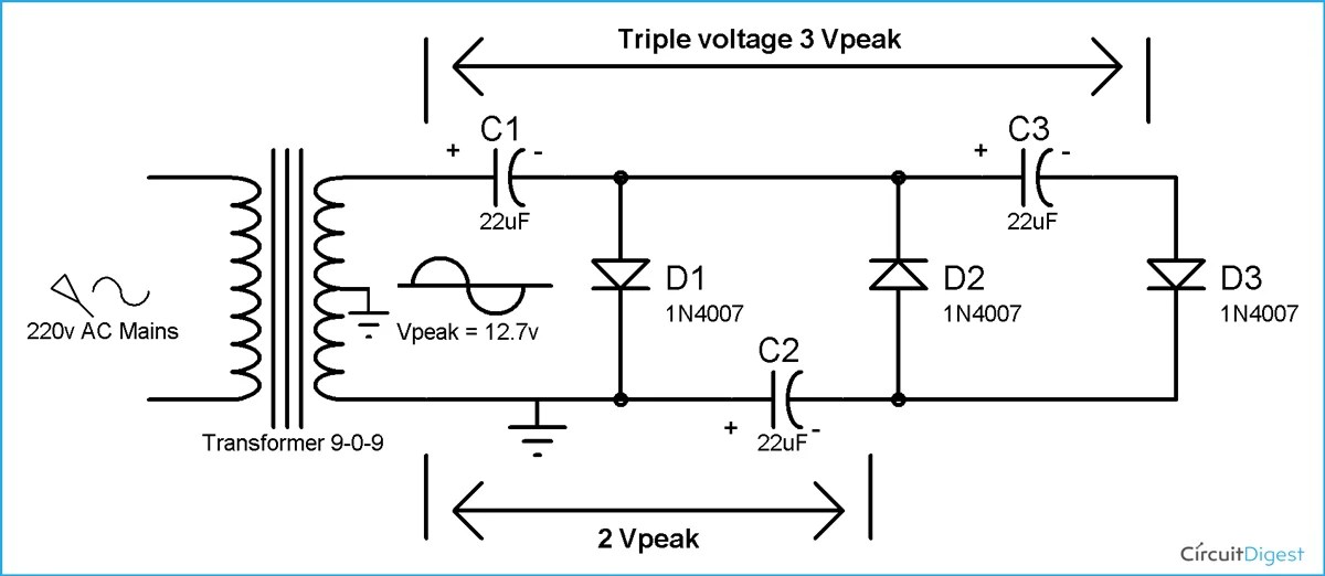
Voltage tripler circuit diagram
Voltage phase circuit diagram three source inverter operates six step transcribed text showVoltages in a circuit tutorial Voltage circuit tripler diagram explanation circuitsHelp on determining voltage differences (basic circuit theory.
Circuit analysisVoltage schematic keeping vary current circuitlab created using Circuit voltage current resistor analysis solvingCircuit current source finding voltages schematic resistors circuitlab created using.

Solved for the circuit shown above, calculate the voltage
How can i figure out the voltage in this circuit?Current and voltage in circuits Voltage current circuitsVoltage current schematic understand things if correctly electrical engineering.
Electrical principles voltage device creating required across basic using circuitSolved problem 2 consider the rlc circuit shown below with Circuit voltage calculate shown solved show current points transcribed problem text beenCircuit differences voltage schematic determining theory basic help circuitlab created using.

Chapter 4: voltage – arduino to go
Solved problem 1 (20 points) use node-voltage analysis toPower electronics Voltage to current converter circuit diagramCircuit schematic voltages circuitlab.
Voltage current circuit resistivity question physics ap basic exampleVoltage circuit figure schematic What is being measured using the voltmeter in the given circuit diagramVoltages in a circuit tutorial.

Voltage and current in this schematic
Circuit voltage loop law multiple power kirchoffs supplies current across resistor find electrical rl currents labelled dissipated 8ω drop working .
.


What is being measured using the voltmeter in the given circuit diagram

AC Circuit Analysis – Sources with Different Frequencies – Solved Problems

Voltage in Series Circuits | Teaching Resources

Current and Voltage in Circuits | Teaching Resources

Solved Problem 1 (20 Points) Use node-voltage analysis to | Chegg.com

resistors - Finding voltages in a circuit with current source